Designing complex software systems can be daunting without a clear blueprint. UML Structural Diagrams provide a visual roadmap, helping developers, architects, and teams understand system architecture, components, and their relationships at a glance. In this guide, we’ll explore what structural diagrams are, why they matter, the main types, and real-world examples to make your modeling easier and more effective.
What Are UML Structural Diagrams?
UML Structural Diagrams are a type of diagram in the Unified Modeling Language that depict the static structure of a system, focusing on its key elements and their relationships. Unlike behavioral diagrams that illustrate system dynamics, structural diagrams in UML provide a clear blueprint of system architecture, highlighting components, classes, objects, and their interconnections.
A UML structural diagram helps developers, architects, and stakeholders visualize how different parts of a system fit together, making complex software systems easier to understand, design, and maintain. Common types include class diagrams, component diagrams, and deployment diagrams, each serving as a foundation for structured system modeling.
Why UML Structural Diagrams Matter
UML Structural Diagrams are essential for software design because they provide a clear view of a system’s static structure, making it easier to plan, document, and maintain complex applications. By mapping classes, components, and their relationships, these diagrams enhance design clarity and support effective collaboration among developers, architects, and stakeholders.
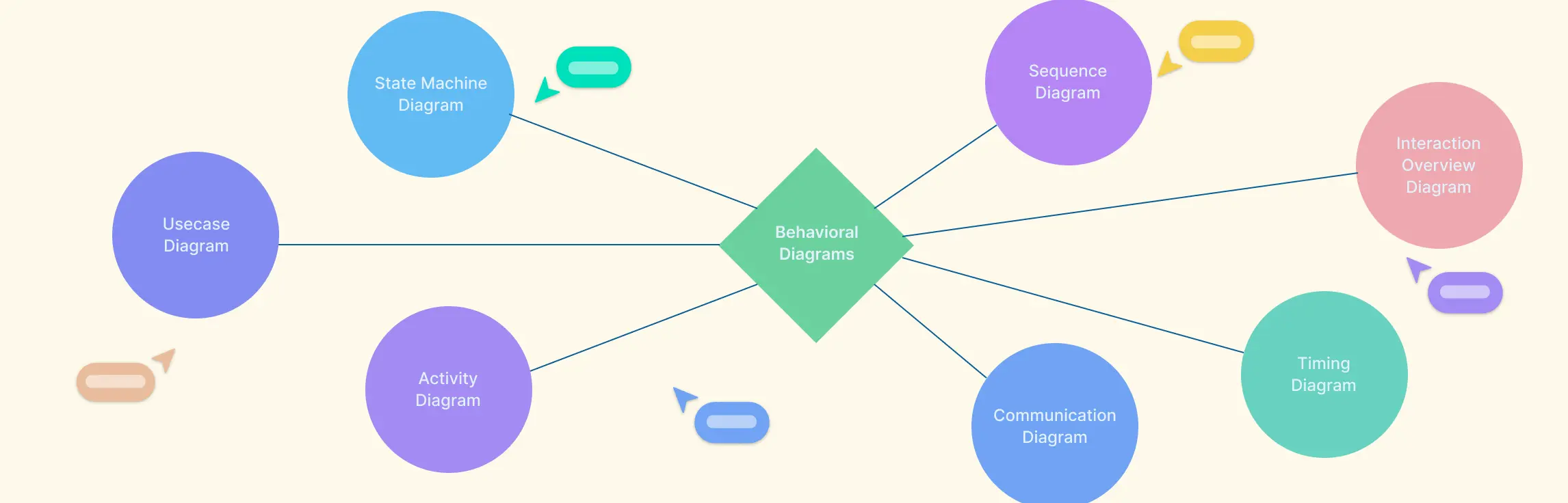
Unlike behavioral diagrams, which focus on system dynamics and workflows, structural diagrams emphasize how the system is built and how its parts interact. For those wondering “what is a behavioral diagram,” it illustrates processes and interactions rather than the underlying architecture. Leveraging UML structural diagrams ensures better system documentation, reduces errors in implementation, and streamlines communication throughout the development lifecycle.
The 7 Types of UML Structural Diagrams
UML Structural Diagrams are used to model the static aspects of a system. Each type focuses on a different perspective, helping developers and architects visualize structure, relationships, and organization. Below are the main types with brief explanations and contextual examples:
1. Class Diagram
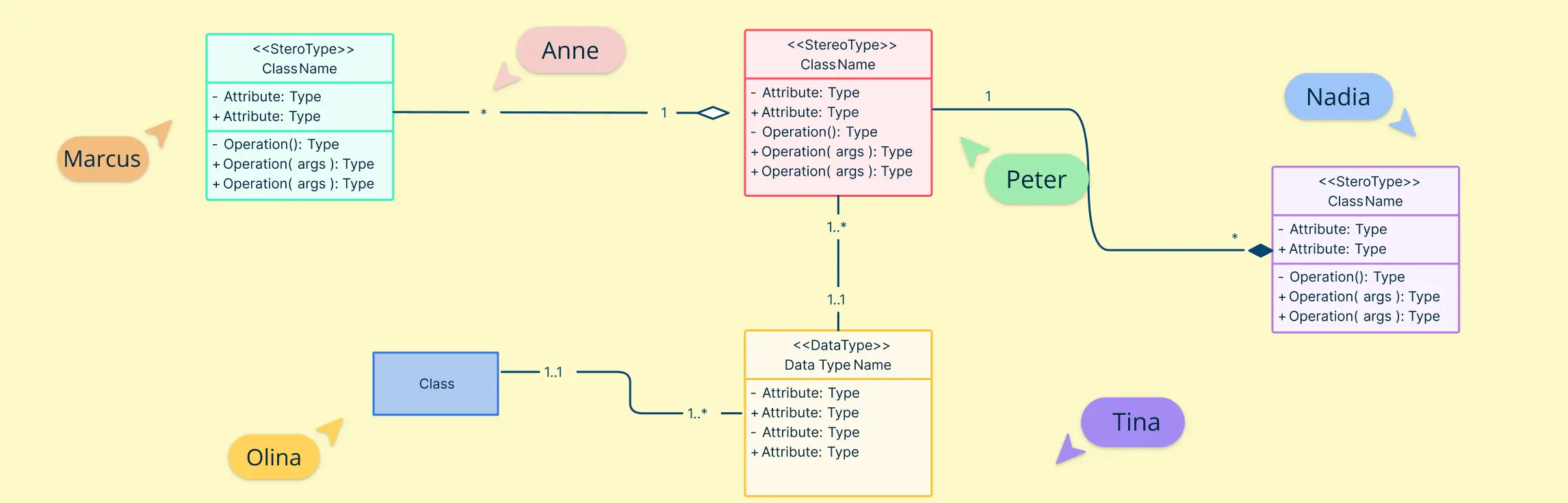
A class diagram is a type of UML structural diagram that provides a detailed view of the static structure of a system by defining its classes, attributes, methods, and relationships. It serves as a blueprint for developers, architects, and stakeholders to understand how the system is organized and how objects will interact at runtime. Class diagrams are particularly useful in object-oriented design because they allow teams to visualize the core building blocks of a system and plan its architecture before coding begins.
Try Creately’s Class Diagram Tool
Key Components of a Class Diagram:
- Classes: Represent the entities in the system (e.g., Customer, Product, Order).
- Attributes: Define the properties of each class (e.g., Customer Name, Product Price, Order Date).
- Methods/Operations: Show the behaviors associated with a class (e.g., placeOrder(), calculateTotal()).
- Relationships: Depict how classes interact, including associations, aggregations, compositions, and inheritances.


2. Object Diagram
An object diagram is a type of UML structural diagram that represents real instances (objects) of classes at a specific moment in time. Unlike class diagrams, which define the system’s blueprint, object diagrams capture the actual runtime state of objects and their relationships, making them invaluable for understanding concrete scenarios and validating system behavior.
Try Creately’s Object Diagram Tool
Key Components of an Object Diagram:
- Objects: Instances of classes (e.g., a specific Customer or Order).
- Attributes: Show the current values of an object’s properties at that moment (e.g., Customer Name = “Alice”, Order Total = $250).
- Links/Relationships: Display the actual connections between objects, reflecting associations, aggregations, or compositions in practice.

3. Component Diagram
A component diagram is a type of UML structural diagram that depicts the software components of a system and the dependencies between them. It focuses on the modular architecture, showing how components interact to form a complete system. Component diagrams are particularly valuable in large or complex applications where understanding the organization of services, libraries, and modules is critical for design, maintenance, and scalability.
Key Elements of a Component Diagram:
- Components: Represent modular parts of the system, such as services, modules, or subsystems (e.g., Payment Service, Inventory Service).
- Interfaces: Define the points of interaction between components, showing provided and required services.
- Dependencies: Show how components rely on each other to function, including usage or communication relationships.
- Artifacts (Optional): Represent physical files, executables, or packages related to components.

4. Deployment Diagram
A deployment diagram is a type of UML structural diagram that illustrates the physical deployment of software components on hardware nodes. It shows how different parts of a system are installed across servers, devices, and networks, making it essential for planning infrastructure, system installation, and runtime configuration. Deployment diagrams are particularly useful for understanding the relationship between software and hardware, ensuring efficient resource allocation, and identifying potential bottlenecks or points of failure.
Key Elements of a Deployment Diagram:
- Nodes: Represent hardware or computational resources such as servers, workstations, or mobile devices.
- Artifacts: Denote physical files, executables, or software components deployed on nodes.
- Communication Paths: Show network connections or communication links between nodes.
- Dependencies: Indicate which nodes host specific software artifacts and how they interact.

5. Package Diagram
A package diagram is a type of UML structural diagram that organizes related UML elements into logical packages to simplify the structure of complex systems. Grouping classes, components, and other elements into packages improves system modularity, enhances readability, and makes it easier to manage large-scale applications. Package diagrams are particularly useful for showing high-level organization without getting bogged down in the details of individual classes or components.
Key Elements of a Package Diagram:
- Packages: Logical groupings of related UML elements, such as modules, subsystems, or layers.
- Dependencies Between Packages: Show how one package relies on another, helping identify coupling and maintain modularity.
- Nested Packages (Optional): Sub-packages can represent more granular groupings within a larger module.

6. Composite Structure Diagram
A composite structure diagram is a type of UML structural diagram that illustrates the internal structure of a class or component, focusing on how its parts, ports, and collaborations interact to fulfill its responsibilities. Unlike other structural diagrams that emphasize high-level architecture, composite structure diagrams provide a detailed view of component internals, making them essential for modeling complex systems with intricate interactions.
Key Elements of a Composite Structure Diagram:
- Parts: Represent internal components or sub-objects that collaborate within a larger class or component.
- Ports: Define points of interaction where a part communicates with other parts or external components.
- Connectors/Links: Show communication paths and relationships between parts and ports.
- Collaborations: Highlight how parts work together to accomplish specific behaviors or operations.

7. Profile Diagram
A profile diagram is a type of UML structural diagram that allows developers to extend UML models using stereotypes, tagged values, and constraints to represent domain-specific requirements. Profile diagrams are especially useful for tailoring UML to specialized fields, ensuring that the model accurately reflects unique business rules, standards, or regulatory needs. By organizing UML elements into logical groups, profile diagrams promote modularity, clarity, and consistency across complex systems.
Key Elements of a Profile Diagram:
- Stereotypes: Custom extensions that add domain-specific meaning to UML elements (e.g., «PatientRecord», «Invoice»).
- Tagged Values: Attributes that provide additional metadata to elements for better context.
- Constraints: Rules that enforce proper usage or relationships of model elements.
- Profile Packages: Logical groupings that organize these extensions for reusability and clarity.

Benefits of Using Structural UML Diagrams
Using UML Structural Diagrams offers numerous advantages for software design, documentation, and collaboration. By providing a visual representation of a system’s static architecture, these diagrams help teams understand complex systems at a glance and make informed design decisions.
Improved System Clarity
Structural diagrams clearly illustrate classes, components, packages, and their relationships, making it easier to understand system architecture.
Better Collaboration
Developers, architects, and stakeholders can collaborate effectively, using diagrams as a common visual language to discuss design choices.
Enhanced Documentation
UML structural diagrams serve as a precise reference for system documentation, aiding future maintenance, updates, and onboarding.
Reduced Errors in Design
By visualizing dependencies and relationships, teams can identify potential design flaws early, minimizing costly mistakes during development.
Supports Scalability and Modularity
Diagrams like component and package diagrams help plan modular and scalable architectures, simplifying system expansion and integration.
Facilitates Communication Across Teams
Complex systems can be communicated effectively to technical and non-technical stakeholders using intuitive visual diagrams.
Challenges Faced in Developing Structural UML Diagrams
While UML Structural Diagrams are invaluable for system design and documentation, creating them can present several challenges, especially for complex projects or large teams. Understanding these challenges can help teams plan better and make diagramming more effective.
Complexity in Large Systems
Modeling extensive systems with numerous classes, components, and packages can become overwhelming and cluttered.
Maintaining Accuracy
Ensuring that diagrams accurately reflect the current system architecture can be difficult, especially if the system evolves rapidly.
Consistency Across Teams
Multiple team members working on different parts of a system may produce inconsistent diagrams without clear standards or guidelines.
Overgeneralization vs. Detail
Striking the right balance between too much detail (making diagrams confusing) and too little (losing critical information) can be challenging.
Tool Limitations
Not all diagramming tools provide the flexibility, templates, or collaboration features needed for efficient UML structural diagram creation.
Learning Curve
For beginners, understanding UML symbols, relationships, and conventions can be intimidating, slowing down the diagramming process.
Despite these challenges, using Creately with pre-built templates and collaboration features can significantly reduce difficulties, allowing teams to create accurate, clear, and maintainable UML structural diagrams.
Best Practices for Developing Structural UML Diagrams
Creating effective UML Structural Diagrams requires a strategic approach to ensure clarity, accuracy, and usability. Following best practices helps teams produce diagrams that are both understandable and actionable.
Define Clear Objectives
Identify the purpose of the diagram before creating it, whether for design planning, documentation, or stakeholder communication.
Use Standard UML Notations
Stick to standard UML symbols and conventions to maintain consistency and ensure diagrams are universally understandable.
Keep Diagrams Simple and Readable
Avoid clutter by breaking complex systems into multiple diagrams or packages to highlight modular structures.
Leverage Templates
Use pre-built templates for class, component, deployment, and other diagrams to save time and maintain consistency.
Iterate and Update Regularly
As the system evolves, update diagrams to reflect changes accurately, ensuring they remain a reliable reference.
Collaborate with Teams
Engage developers, architects, and stakeholders in diagram creation and review to capture all perspectives and reduce errors.
Balance Detail and Abstraction
Include enough detail to convey meaningful information without overwhelming viewers with unnecessary complexity.
Mastering UML Structural Diagrams empowers you to design systems with clarity, structure, and scalability. By understanding the different types, from class and object diagrams to component, deployment, and profile diagrams, you can document and communicate complex systems effectively. Ready to create your own diagrams and streamline system design? Try Creately’s UML Diagram Tool today and explore our customizable UML structural diagram templates to visualize your architecture effortlessly.